Crankcase Assembly
SAFETY FIRST: Protective gloves and eyewear are recommended at this point.
Thoroughly clean the crankcase mating surfaces.
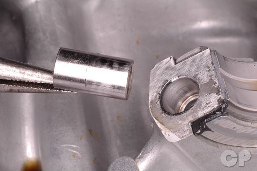


Install the dowel pins into the upper crankcase half.
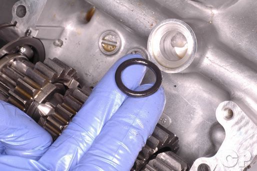


Install new O-rings.
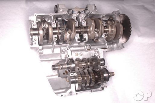
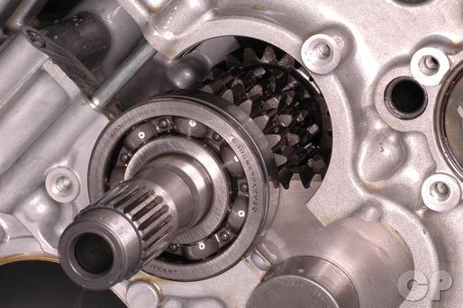
Set the upper crankcase half assembly upside down so that the crankshaft and transmission shafts face up.


Apply Suzuki Bond or equivalent silicone sealant to the lower crankcase half mating surface.
Suzuki Bond 1207B: 99104-31140


Fit the lower crankcase half onto the upper crankcase half.
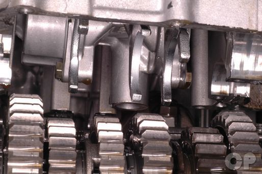 Fit the shift forks into their correct gear grooves. The two outside shift forks fit in the grooves on the C5 and C6 countershaft gears. The middle shift fork fits in the groove on the M3/4 combo gear on the mainshaft.


Make sure the studs and dowel pins line up correctly.
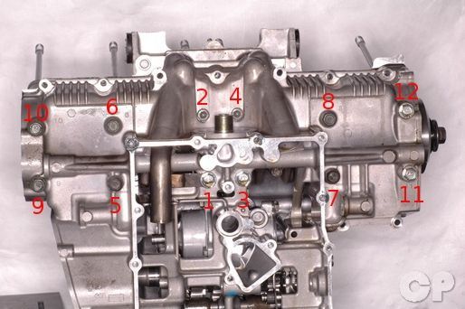
Insert the 12 crankcase bolts.


Install new sealing washers with the number 9 and 11 bolts.


Install the oil pipe with the number one bolt.


Tighten the number two and four bolts with a 6 mm Allen.


Tighten the rest of the bolts with a 12 mm socket.
The bolts must be tightened evenly. Turn in the bolts a little bit at a time and work in an ascending order. Tighten the all the bolts to the initial torque and then repeat the tightening process to torque them to the final specification. The Allen bolt torque specifications only apply to the 750 models. Torque all of the bolts to the same specification on the 600 models.
(Crankcase Bolt Initial Torque: 13 N-m or 9.5 lb-ft)
(Crankcase Allen Bolt Initial Torque: 14 N-m or 10 lb-ft)
(Crankcase Bolt Final Torque: 23 N-m or 16.5 lb-ft)
(Crankcase Allen Bolt Final Torque: 24 N-m or 17.5 lb-ft)


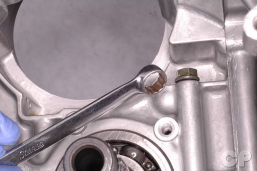
Install a new O-ring onto the main oil galley plug. Install the oil galley plug and tighten it to specification with an 8 mm Allen.
(Main Oil Galley Plug Torque: 40 N-m or 29 lb-ft)


Install the rear crankcase bolt and nut.


Insert the left lower crankcase bolts. Install a new sealing washer with the outside bolt.


Thread in the seven forward lower crankcase bolts.


Tighten the lower crankcase bolts and nut evenly to the initial torque specification. Tighten the rear bolt with a 12 mm socket, the nut with a 10 mm wrench, and the rest of the bolts with a 10 mm socket. Evenly torque the bolts to their final specification.
(Lower Crankcase Nut and Bolt Initial Torque: 6 N-m or 4.5 lb-ft)
(Lower Crankcase Nut and Bolt Final Torque: 11 N-m or 8.0 lb-ft)


Insert the three upper crankcase Allen bolts.


Insert the four other upper crankcase bolts and thread on the nut.


Tighten the Allen bolts evenly to the initial specification. Torque the bolts to final specification with a 5 mm Allen.
(750 Upper Crankcase Allen Bolt Initial Torque: 7 N-m or 5.0 lb-ft)
(600 Upper Crankcase Allen Bolt Initial Torque: 6 N-m or 4.5 lb-ft)
(750 Upper Crankcase Allen Bolt Final Torque: 14 N-m or 10 lb-ft)
(600 Upper Crankcase Allen Bolt Final Torque: 11 N-m or 8.0 lb-ft)
Install the plug over the Allen bolt near the mainshaft on the 750 models.


Tighten the other upper crankcase bolts evenly to the initial torque specification. Torque the bolts to the final specification with a 10 mm socket.
(Upper Crankcase Bolt Initial Torque: 6 N-m or 4.5 lb-ft)
(Upper Crankcase Bolt Final Torque: 11 N-m or 8.0 lb-ft)
Tighten the upper crankcase nut to specification with a 10 mm wrench.
(Upper Crankcase Nut Torque: 11 N-m or 8.0 lb-ft)


Install the oil return pipe. Tighten its bolt securely with a 10 mm socket.
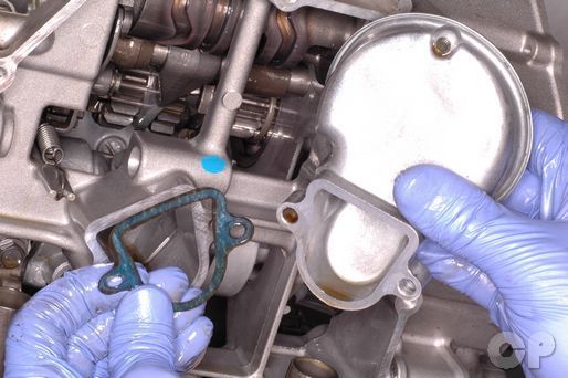
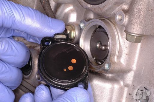
Install the oil sump filter with a new gasket.


Tighten the two oil sump filter mounting bolts securely with a 10 mm socket.
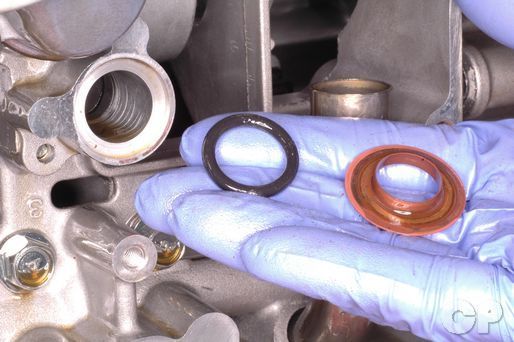
Install a new O-ring and shim into the orifice.


Install a new oil pan gasket and the oil pan.
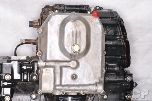


Install the 14 oil pan bolts. Use a new sealing washer with the indicated bolt. Tighten the bolts to specification evenly with a 10 mm socket.


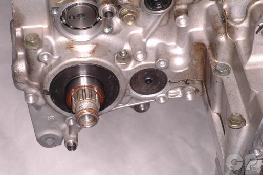
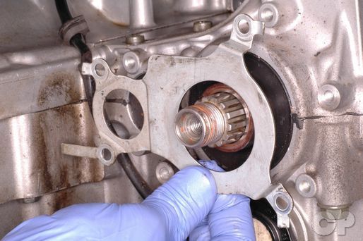
Apply blue Loctite to the threads of the mainshaft bearing retainer plate screws. Install the mainshaft bearing retainer plate. Tighten the screws securely with a # 3 Phillips screwdriver.


Install the neutral switch contact and spring into the shift drum.
Install a new O-ring onto the neutral switch.


Install the neutral switch and tighten its two mounting screws securely with a #2 Phillips screwdriver.


Install the countershaft seal retainer. The neutral switch wires should run behind the retainer as shown. Install the four countershaft seal retainer bolts and tighten them securely with a 10 mm socket.


Bend the retainer tabs against the three bolts with a punch and a hammer.
Install the starter clutch and idle gear. See the Starter Clutch topic for more information.
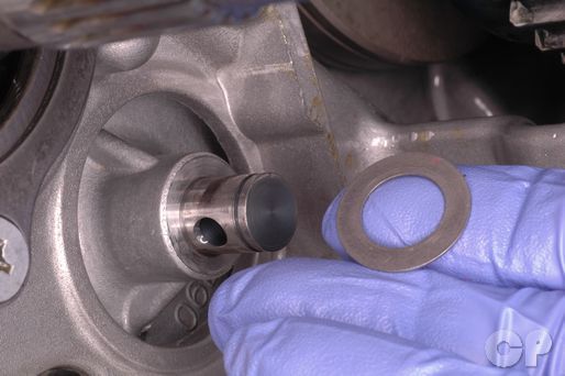


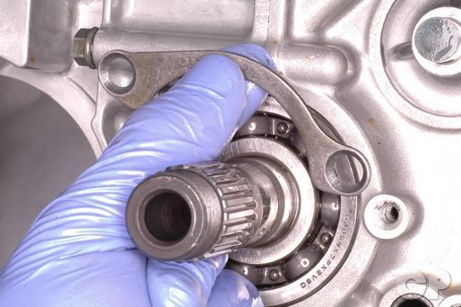
Install the washer and oil pump driven gear pin.
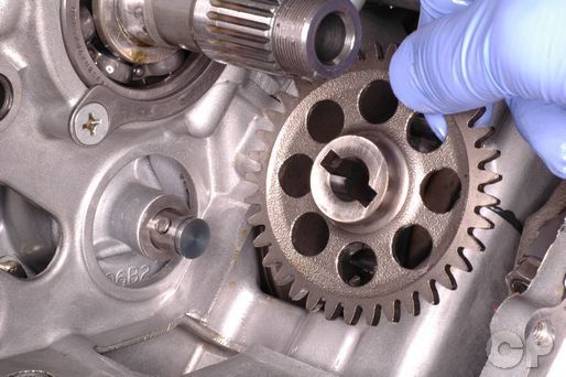


Install the oil pump driven gear and washer. Install the snap ring into the groove with snap ring pliers.
Install the gearshift. See the Gearshift topic for more information.
Install the clutch. See the Clutch Installation topic for more information.
Install the signal generator and oil pressure switch. See the Signal Generator topic for more information.
Install the generator. See the Generator topic for more information.
Install the starter motor. See the Starter Motor topic for more information.
Install the cylinder and pistons. See the Cylinder and Pistons topic for more information.
Install the cylinder head. See the Cylinder Head Installation topic for more information.
Return the engine to the frame. See the Engine Installation topic for more information.
Copyright 2025 - Cyclepedia Press LLC

Note: If you are viewing this document offline be sure to visit the latest version online at http://www.cyclepedia.com before attempting any repairs. Updates are made without notice.